Seal Clearance Reductions: How Smaller Gaps Improve Shaft Sealing Performance
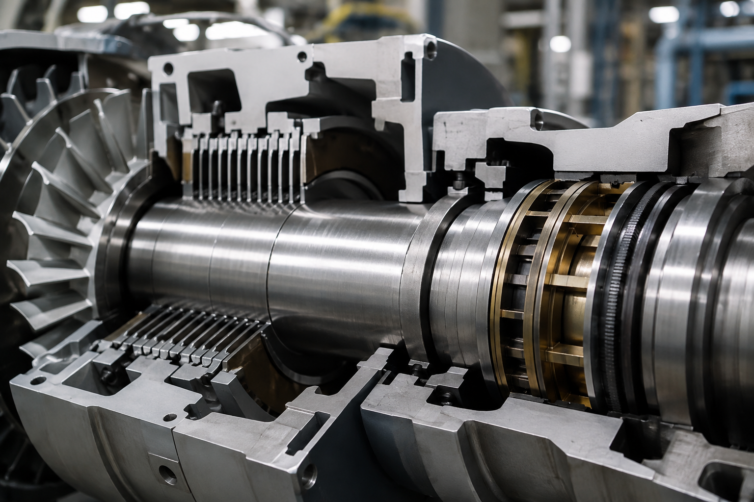
Rotating machinery depends on controlled clearances to manage the movement of gases, steam, air, or process fluids between areas operating at different pressures. Even a small unwanted gap can create a leakage path, reducing machine efficiency and affecting the performance of nearby components.
Seal clearance reductions focus on decreasing the space between rotating and stationary sealing surfaces to limit this leakage. The objective is not simply to make a gap as small as possible. The clearance must be selected according to shaft movement, thermal expansion, component geometry, operating speed, and the properties of the working fluid.
This balance makes clearance design a practical engineering consideration rather than a simple dimensional adjustment.
How Clearance Affects Leakage
Fluid naturally moves through available openings when a pressure difference exists. In rotating machinery, excessive clearance can allow more fluid to pass through a sealing area than the equipment design permits.
A larger gap generally creates a less restrictive leakage path. Reducing that gap increases resistance to flow and can help maintain pressure separation between adjacent sections of the machine.
The effect depends on several factors, including:
- Pressure difference across the seal
- Fluid density and temperature
- Rotational speed
- Shaft diameter
- Seal geometry
- Surface finish
- Operating clearances
- Thermal growth
- Shaft vibration and movement
For this reason, engineers typically evaluate the complete operating range instead of designing around a single operating condition.
Where Seal Clearance Reductions Are Used
Clearance control is common in turbines, compressors, pumps, expanders, and other rotating equipment where leakage can affect performance.
In compressors, controlled clearances can reduce the amount of compressed gas escaping from high-pressure regions. In turbines, maintaining appropriate gaps can help control steam or gas leakage around rotating stages. Similar principles apply to pumps and other equipment that depend on pressure differentials.
The required clearance can vary considerably from one machine to another. A high-speed turbine may require different allowances for thermal expansion and rotor movement than a slower industrial pump.
Engineers therefore consider the machine’s complete operating envelope before specifying the final dimensions.
The Connection Between Clearance and Shaft Sealing
Shaft sealing prevents or limits fluid from moving along a rotating shaft or escaping from the equipment casing. Clearance is one of the physical characteristics that influences how effectively the sealing arrangement performs.
A seal with excessive clearance may allow leakage to increase. A clearance that is too tight, however, can create another set of problems. Rotor contact, friction, heat generation, and component damage can occur if normal shaft movement eliminates the intended operating gap.
A practical design therefore leaves enough space for expected movement while restricting unnecessary leakage.
Temperature also matters. Components can expand as the machine reaches operating conditions, changing the gap from its cold assembly dimension. Designers may account for this change by modeling thermal expansion and establishing operating clearances that remain suitable after the machine reaches temperature.
Brush Seals and Clearance Control
Brush seals use closely packed flexible bristles to restrict fluid movement around rotating components. The bristles can accommodate small amounts of rotor movement while maintaining a relatively narrow sealing interface.
Compared with conventional larger-clearance arrangements, brush seals can provide a tighter leakage path. Their design must account for bristle stiffness, rotor speed, pressure difference, temperature, and possible contact with the rotating surface.
The clearance between the brush and rotor is especially relevant during startup, shutdown, and transient conditions. A small amount of controlled contact may occur in some designs, but excessive rubbing can shorten seal life and damage the rotor surface.
Manufacturing accuracy and installation quality also affect performance. Misalignment or improper positioning can change the effective clearance around the shaft.
Honeycomb Seals in High-Speed Machinery
Honeycomb seals use a honeycomb-patterned structure that creates a restrictive flow path between the stationary seal and rotating surface. They are frequently associated with turbomachinery applications where leakage control and rotor dynamics must be considered together.
The honeycomb structure disrupts the fluid flow and can provide damping characteristics that are useful in certain rotating machinery designs. The seal geometry, cavity dimensions, pressure conditions, and clearance all contribute to its behavior.
Clearance reduction can improve leakage control, but reducing the gap without considering rotor movement can increase the possibility of rubbing. Engineers must therefore evaluate both fluid performance and mechanical behavior.
For high-speed equipment, rotor dynamics analysis can help determine how much movement may occur during normal operation and under transient conditions.

Stationary Components and Their Sealing Interfaces
Stationary parts sealing involves controlling leakage around components that do not rotate, including casings, covers, partitions, and other fixed structures.
These interfaces may use gaskets, O-rings, labyrinth arrangements, metallic seals, or other sealing methods depending on pressure, temperature, fluid type, and maintenance requirements.
Although stationary components do not experience rotational motion, thermal expansion and pressure loading can still change the sealing interface. Surface condition, fastener loading, component flatness, and material selection may affect long-term sealing performance.
Clearance management can also matter where stationary and rotating components operate close to one another. The stationary structure must maintain its position while allowing sufficient space for the rotating assembly to operate safely.
Finding the Right Clearance
The ideal clearance is a compromise between leakage control and mechanical reliability. Engineers commonly consider several operating conditions before selecting a value.
Rotor deflection is one consideration. A shaft may move slightly under load, and bearings may permit limited radial or axial movement. Thermal growth is another. Different materials may expand at different rates as temperature changes.
Manufacturing tolerances must also be included. A theoretical clearance may not represent the actual gap after machining, assembly, coating application, and component installation.
Surface roughness can affect the practical behavior of a narrow sealing interface as well. A design that appears acceptable dimensionally may perform differently if the mating surfaces have unexpected wear or irregularities.
Inspection and Maintenance Considerations
Maintaining the designed clearance requires periodic inspection. Wear, deposits, corrosion, erosion, shaft movement, and previous contact can change the original geometry.
During maintenance, technicians may measure seal dimensions and compare them with manufacturer specifications or established maintenance limits. Inspection can also reveal signs of rubbing, such as scoring or polished contact areas.
Monitoring leakage, vibration, temperature, and machine efficiency can provide additional information about changing seal conditions.
For equipment operating under demanding conditions, maintenance records can help identify gradual changes rather than waiting for a significant performance problem.
The Role of Engineering Analysis
Modern seal design often combines fluid-flow calculations, rotor-dynamics studies, thermal analysis, and tolerance assessment. These methods allow engineers to examine how a proposed clearance behaves under different operating conditions.
A clearance that performs well at steady-state speed may behave differently during startup or shutdown. Pressure fluctuations, temperature changes, shaft deflection, and vibration can all alter the relationship between stationary and rotating surfaces.
That is why seal clearance reductions should be evaluated as part of the complete machine design rather than treated as an isolated dimensional change.
Practical Considerations Before Reducing Clearance
Before reducing a sealing gap, engineers should review:
- Expected shaft movement
- Rotor and casing thermal expansion
- Operating pressure and temperature
- Rotational speed
- Manufacturing tolerances
- Surface finish
- Existing wear patterns
- Potential rotor-to-seal contact
- Maintenance requirements
- Leakage limits
These factors help establish a clearance that supports both leakage control and dependable operation.
A Balanced Approach to Seal Design
Reducing unnecessary clearance can limit fluid leakage and support equipment efficiency, but smaller gaps are not automatically better. The correct dimension depends on the machine, materials, operating conditions, seal design, and expected movement.
For rotating equipment, successful sealing comes from controlling the space between components without creating unacceptable friction or contact. Careful dimensional control, appropriate seal selection, accurate manufacturing, and regular inspection all contribute to maintaining that balance.
Seal clearance reductions are therefore best viewed as an engineering design practice that connects leakage control with mechanical reliability, thermal behavior, and long-term equipment operation.